A relay that looks fine can still fail under load, and that can make a simple electrical problem hard to find. If you want to know How to Test a Relay With a Multimeter, the good news is that the process is usually straightforward once you know which terminals matter and what readings to expect.
This guide walks you through the full test in clear steps. You will learn how to identify the relay pins, check the coil, test the switch contacts, and spot the difference between a bad relay and a wiring problem. You will also see the most common mistakes people make, so you can avoid false readings and wasted time.
The method below works for many 4-pin and 5-pin relays used in cars, trucks, tools, and home equipment. A digital multimeter is enough for the basic checks, and a simple power source helps with the final activation test.
What You Need Before You Start
Before you test anything, make sure you have the relay removed from the circuit and identified correctly. A relay is just an electrically controlled switch, but the pin layout can vary by model, so guessing is a bad idea.
You will need a digital multimeter, the relay itself, and usually a 12-volt power source for an activation test if you want to go beyond resistance checks. A small fused jumper wire is helpful too, because it protects the circuit if you need to energize the coil briefly.
If you are testing automotive relays, the relay case often shows a diagram with pin numbers such as 85, 86, 30, 87, and sometimes 87a. If that diagram is missing, you can still test the relay, but you will need to identify the coil and contact terminals by measurement instead of by label.
Helpful tools and safety basics
- Digital multimeter with resistance and continuity modes
- 12V power source for activation testing, if needed
- Fused jumper leads to reduce short-circuit risk
- Relay pin diagram from the relay body, datasheet, or equipment manual
- Safety glasses if you are working around battery power
Keep the relay away from metal tools while testing. A quick short across the wrong pins can damage the relay, blow a fuse, or confuse your readings.
Why relay failures are easy to miss
One relay can fail in more than one way. The coil may be open, the contacts may be burned, or the relay may work cold but fail when warmed up. That is why a single test is not always enough.
Another detail many beginners miss is that a relay can click and still be bad. The click only means the coil moved the internal armature. It does not prove the power contacts are actually passing current.
Identify the Relay Terminals Correctly
Testing starts with terminal identification. If you mix up the coil pins and the contact pins, your meter readings will not mean much.
Most standard relays have two coil terminals and two or three switch terminals. In many automotive relays, 85 and 86 are the coil, 30 is the common input, 87 is the normally open output, and 87a is the normally closed output when present.
Common relay pin functions
| Pin | Typical function | What it means during testing |
|---|---|---|
| 85 | Coil terminal | Usually one side of the electromagnetic coil |
| 86 | Coil terminal | Other side of the coil |
| 30 | Common terminal | Input side of the switched circuit |
| 87 | Normally open contact | Should connect to 30 only when the relay is energized |
| 87a | Normally closed contact | Should connect to 30 when the relay is not energized |
Some relays use different markings, especially industrial and appliance relays. If the numbering is not obvious, use the relay diagram on the case, or look for the manufacturer’s official owner’s manual, manufacturer datasheet, or support page for the exact pinout and coil voltage.
A useful shortcut: the coil terminals usually show some measurable resistance, while the contact terminals often show open circuit until the coil is energized. That difference helps you separate the two groups fast.
What the relay type changes
A 4-pin relay usually has a coil and one switched output path. A 5-pin relay adds the normally closed contact, which means you will see a second contact path in the unpowered state.
Some relays are sealed and tiny, with lower coil resistance than larger power relays. Others are designed for heavy loads and may have more contact resistance when idle. The testing method stays the same, but the exact numbers can vary by design.
Check the Coil With the Multimeter
The first real test is the coil. If the coil is open or shorted, the relay cannot switch properly even if the contacts look fine.
Set your multimeter to resistance mode, usually marked as Ω. Touch the probes to the two coil terminals. A healthy relay coil usually shows a steady resistance value instead of infinite resistance or zero.
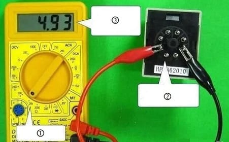
Credit: aliontimer.com
How to read the coil result
- Infinite resistance or OL: the coil is open, and the relay is likely bad
- Very low resistance near 0 Ω: the coil may be shorted, which is also a failure
- Moderate resistance: often normal, depending on relay design
For many 12V automotive relays, coil resistance often falls somewhere around 50 to 200 ohms. That is a common range, not a universal rule. Small signal relays can be higher, and some heavy-duty relays can be lower.
A non-obvious point many people miss: resistance can change slightly as the coil warms up, but it should not jump wildly. If the reading drifts a lot just from touching the probes, the relay may have an internal break.
What to do if your reading looks odd
If the meter shows no stable value, clean the relay pins and try again. Oxidized terminals can cause poor probe contact and create a false bad reading.
If the coil reads near zero, disconnect the relay immediately and do not energize it. A shorted coil can draw too much current and may blow a fuse or overheat a jumper wire.
Test the Switch Contacts With Resistance and Continuity
Once the coil looks reasonable, check the contact side. This tells you whether the relay is actually opening and closing the circuit the way it should.
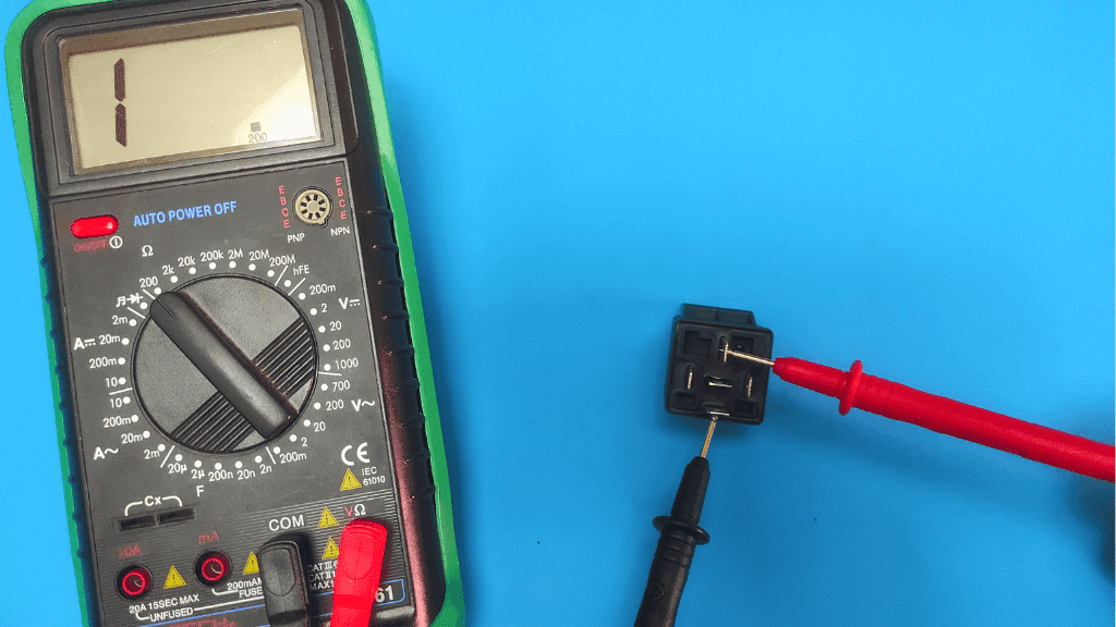
With the relay unplugged and unpowered, measure between 30 and 87 on a normally open relay. You should usually see open circuit or no continuity. If it is a 5-pin relay, measure between 30 and 87a instead and expect continuity in the unpowered state.
What the contact test should show
- 30 to 87 on a normally open relay: open when unpowered
- 30 to 87a on a normally closed relay: closed when unpowered
- 30 to 87 after energizing: should close with low resistance
- 30 to 87a after energizing: should open
Use continuity mode if your meter has it. A good relay often gives a beep when the contacts close. Still, do not trust the beep alone. Some meters beep through slightly dirty or weak connections, so the actual resistance reading matters too.
When the contacts are closed, the reading should be very low, often below 0.5 ohm on a clean relay. In practice, lead resistance can affect low-ohm readings, so the exact number is less important than the change from open to closed.
Why a relay can click but still fail this test
The coil can move the internal armature and make an audible click, but burned or pitted contacts may still block current. That is one reason a quick sound check is not enough.
If the relay controls a high-load device like a fan or compressor, contact wear is common. High current arcs slowly damage the contact surface, and the relay may fail only when load is high even though it seems fine on the bench.
Energize the Coil and Confirm the Relay Switches
This is the most useful live test. It confirms not just that the coil has resistance, but that the relay actually changes state when power is applied.
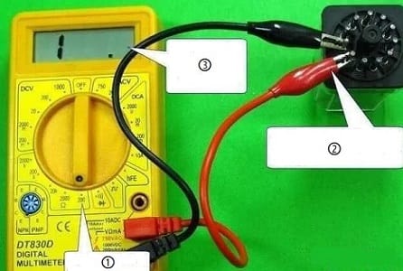
Apply the correct coil voltage to the coil pins, usually 12 volts for automotive relays, but check the relay marking first. You should hear or feel a click, and the contact readings should change immediately.
How to perform the activation test
- Connect a fused jumper to the coil terminal that should receive power.
- Connect the other jumper to the remaining coil terminal and ground or negative, depending on the relay type.
- Touch power for just a second or two.
- Listen for a click and check the contact terminals again.
- Remove power right away after the test.
If the relay is healthy, the normally open contact should close and the normally closed contact should open, if present. If the relay does not click, the coil may be bad, the voltage may be wrong, or the jumper connection may be poor.
One important insight: a relay can click at 12V and still fail under actual vehicle voltage if the coil is weak. Real-world charging systems can vary, and some relays only behave reliably when coil voltage is stable. That is why the contact test under energization matters more than the click alone.
How to avoid damaging the relay
Do not hold voltage on the coil for longer than needed during a test. Most relays can tolerate normal operation, but a bad relay may overheat if it is already damaged.
Also, use the correct polarity only if the relay design requires it. Many simple relays do not care about coil polarity, but some include suppression diodes, and reversing polarity can short the coil supply.
How to Tell If the Relay Is Bad or the Problem Is Elsewhere
Relay testing is only half the job. You also need to know whether the relay is the real failure or just the messenger for another electrical problem.
If the relay tests good on the bench, the problem may be in the socket, wiring, fuse, control signal, or load device. That is why checking the relay alone is not always enough to fix the system.
Credit: electrouniversity.com
Quick diagnostic clues
- No coil resistance usually means a bad relay
- Good coil, no click with proper power suggests coil or power issue
- Clicking relay, no output points to burned contacts or socket wiring
- Relay works off the vehicle but not installed suggests socket or control-side trouble
Check the relay socket next. Corrosion, loose terminals, or heat damage can stop a good relay from working. A relay with shiny contacts can still fail in a melted socket because the terminal grip is weak.
Also test for voltage at the control side if the relay is in a machine or vehicle. Many beginners replace the relay first, but the actual problem is sometimes a bad ground, a blown fuse, or a missing trigger signal from a switch or control module.
Common mistakes that lead to false conclusions
One common mistake is testing the relay while it is still plugged into the circuit. That can give you readings through other components and make a good relay look bad.
Another mistake is using the wrong meter setting. Continuity mode is useful, but resistance mode gives better detail. If you use the wrong range or leave the probes loose, you can easily mistake a poor connection for a relay failure.
Common Relay Testing Mistakes and How to Fix Them
Small testing errors are responsible for many false diagnoses. Fixing those mistakes often saves more time than replacing parts.
1. Mixing up coil and contact pins
Always identify the coil first. If you measure between contact terminals, you may see open circuit and think the relay is bad, when you are simply on the wrong pins.
2. Trusting the click only
A click means movement, not good current flow. Always verify the contact readings after the relay is energized.
3. Testing with dirty terminals
Oxidation can create unstable readings. Clean the relay legs and meter probes if the result changes each time you touch them.
4. Using weak jumper wires
A thin or damaged jumper can drop voltage under load. That can make a good relay seem weak, especially during the activation test.
5. Forgetting about the socket
If the relay passes on the bench, check the socket terminals for spread contacts, rust, heat marks, or melted plastic. Many relay problems are actually connection problems.
These are the kinds of issues beginners often miss because the test seems simple. In reality, the quality of the setup matters as much as the relay itself.
Practical Example: Testing a Standard 12V Automotive Relay
Here is a simple example. You have a 5-pin relay from a vehicle fan circuit, and the fan does not run. The relay clicks when the system is turned on, but the fan still stays off.
First, measure the coil between 85 and 86. You get 78 ohms, which is a reasonable value for many 12V relays. Next, check 30 to 87a with no power applied and see continuity. That part is normal for a normally closed path.
Then you apply 12 volts to the coil. The relay clicks, and 30 to 87a opens while 30 to 87 closes with very low resistance. That means the relay itself is probably good, so the problem is likely wiring, fuse, socket, or the fan motor.
If the coil had shown OL instead of 78 ohms, the relay would have been bad. If the relay clicked but 30 to 87 never closed, the contacts were likely burned. That simple sequence separates a bad relay from a bad circuit very quickly.
When the Relay Needs Replacement
Replace the relay if the coil is open, the coil is shorted, or the contacts do not switch properly under power. Replace it if the relay works only intermittently after tapping it or if the case shows heat damage.
There is no point trying to “save” a relay with burned contacts in most situations. Relays are usually inexpensive compared with the time spent chasing unstable electrical symptoms.
Before installing a new relay, fix the cause of failure if possible. A relay that died from excessive current, poor grounding, or a stuck load can fail again fast if the root problem stays in place.
If you want deeper safety and handling guidance for electrical devices, use the equipment’s official safety guidance when working around energized systems.
Credit: aliontimer.com
Final Check Before You Put Everything Back
Before reinstalling the relay, compare the old relay to the new one. The pin layout, coil voltage, and contact rating should match. A 12V relay with the wrong terminal pattern can fit poorly or operate incorrectly.
Also inspect the socket for heat damage. A relay may test perfectly and still fail early if the socket connection is loose. A loose terminal creates extra resistance, and extra resistance creates heat.
That is the hidden part many people miss. The relay is often not the only problem; it is sometimes the first part to reveal a bigger circuit issue.
Now you know How to Test a Relay With a Multimeter the right way: check the coil, check the contacts, energize the relay, and compare the results to the real circuit. With a few careful measurements, you can spot a bad relay fast and avoid replacing parts that still work.
If the relay is part of a bigger control problem, it also helps to know how to test a switch with a multimeter and how to test a wire with a multimeter. Those two checks make it easier to tell the difference between a bad relay, a bad switch, and a broken wire.
Safety note: Disconnect power before using ohms or continuity mode on a relay. Only apply test power when the relay is isolated and the voltage matches the coil rating.
FAQs
1. What setting should I use on my multimeter to test a relay?
Use resistance mode for the coil and continuity or resistance mode for the contacts. Resistance mode is better when you want to see a clear ohm value, while continuity mode helps confirm whether the contacts close.
2. Can a relay click and still be bad?
Yes. The click only means the coil moved the internal switch. The contacts can still be burned, pitted, or dirty, so the relay may not pass current even though it sounds normal.
3. What resistance should a 12V relay coil show?
Many 12V automotive relay coils fall somewhere around 50 to 200 ohms, but the exact value depends on the relay design. Always compare your reading with the relay’s label or datasheet when possible.
4. Can I test a relay without removing it?
You can do some voltage checks in place, but bench testing is more reliable. Testing the relay outside the circuit removes interference from wiring, fuses, and connected components.
5. What if the relay tests good but the equipment still does not work?
Then the problem is likely in the socket, wiring, control signal, fuse, ground path, or the load device itself. Check the circuit step by step instead of replacing the relay again.