If a wire is bad, a multimeter can tell you fast. How to Test a Wire With a Multimeter is simple once you know which mode to use and what reading to trust.
The key is not just touching the probes to the wire. You also need to know whether you are checking continuity, resistance, or voltage. Each test answers a different question, and using the wrong one can give you a confusing result.
This guide shows the exact steps, the right settings, and the common mistakes that cause false readings. You will also learn how to test a wire inside a cable, how to spot a broken conductor, and when the problem is not the wire at all.
What you need before you start
Before testing, make sure the circuit is safe and the wire is accessible. A multimeter can only give a useful reading if the wire is isolated enough for the test you want to perform.
For most wire checks, you only need a digital multimeter, two test leads, and basic access to both ends of the wire. If the wire is part of a live circuit, you may also need the power source turned off before using continuity or resistance mode.
Tools and safety basics
- Digital multimeter with continuity and resistance settings
- Test leads that are in good condition
- Wire access points at both ends, if possible
- Insulated gloves if you are working near live electrical parts
- Power off for continuity and ohm tests
If you are unsure whether a circuit is live, test the multimeter on a known source first. That small habit prevents one of the most common beginner mistakes: assuming a wire is dead when it is not.
For electrical safety guidance, the official OSHA electrical safety guidance is a useful reference before working around live wiring.
Choose the right test for the problem
Not every wire problem needs the same test. A continuity test checks whether electricity can pass through the wire. A resistance test shows how much the wire is resisting current. A voltage test checks whether power is present in the circuit.
This matters because a wire can still “look fine” and fail one test. For example, a wire with a partial break may beep in continuity mode but still fail under load. That is why wire testing is more than just listening for a beep.
| Test | What it tells you | Best use |
|---|---|---|
| Continuity | Whether the wire is connected end to end | Finding breaks, open circuits, bad connectors |
| Resistance | How much the wire resists current | Checking for damage, corrosion, or extra resistance |
| Voltage | Whether power is present at a point | Checking if a wire is receiving power |
For most people learning How to Test a Wire With a Multimeter, continuity is the first and easiest test. It gives a quick answer when you want to know if a wire is open or intact.
When continuity is the best choice
Use continuity mode when the wire should connect two points directly, like a car speaker wire, a fuse path, or a cable conductor. If the multimeter beeps, the connection is usually good. If it stays silent, the wire may be broken, disconnected, or not making contact at the probe points.
One non-obvious detail: some meters beep even when resistance is higher than expected, not just when the wire is perfect. A long wire, a corroded terminal, or a weak splice can still trigger a beep, so do not stop at the sound alone.
How to test a wire with a multimeter step by step
Start with the simplest test first. In most cases, a continuity check will tell you whether the wire is open or complete in less than a minute.
1. Turn off the power
Switch off the device, unplug it, or disconnect the battery before testing continuity or resistance. These tests send a small signal through the wire, and live power can damage the meter or create a false reading.
If you are checking a vehicle wire, disconnect the battery if the test allows it. If that is not practical, make sure the specific circuit is dead before moving forward.
2. Set the multimeter to continuity or ohms
Turn the dial to the continuity symbol, which often looks like a sound wave or diode-style icon. If your meter does not have continuity, use the lowest resistance range, usually marked as Ω.
Continuity is easiest because many meters beep when the path is complete. Resistance mode gives a numeric reading, which is helpful when you want more detail than a simple yes or no.
3. Test the meter first
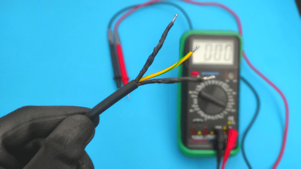
Touch the two probes together. In continuity mode, the meter should beep or show a very low reading. In resistance mode, it should read close to 0 ohms, often 0.1 to 1.0 ohms depending on the meter and lead quality.
This quick check confirms the meter is working. If you do not test the meter first, you may waste time blaming the wire when the real issue is a dead battery in the meter or a bad lead.
4. Place one probe on each end of the wire
Touch one probe to one end of the wire and the other probe to the opposite end. For best results, make contact with bare metal, not insulation. If the wire is in a connector, probe the exposed terminal points.
Hold the probes steady. Flaky contact can make a good wire seem bad. If needed, clip the probes in place with alligator clips so your hands are not creating movement during the test.
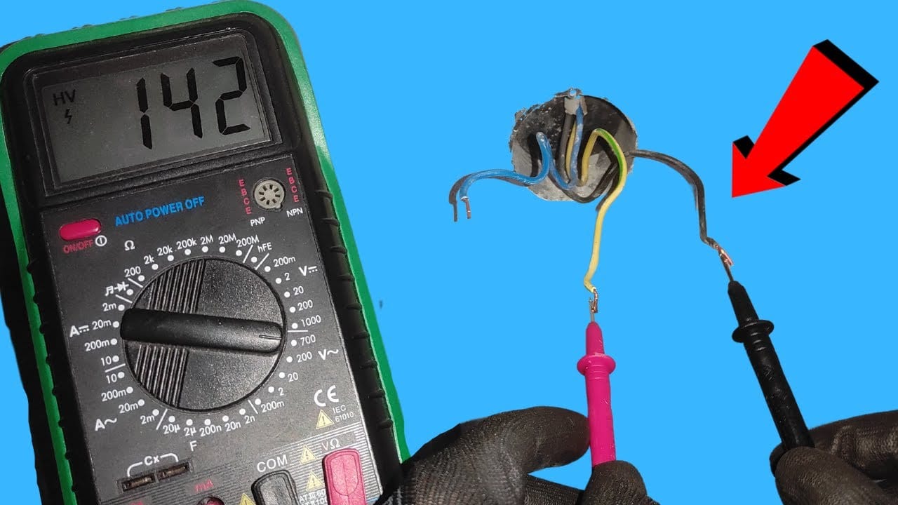
5. Read the result
If the meter beeps or shows very low resistance, the wire has continuity. If the reading stays at OL, 1, or infinity, the wire is open and the circuit is broken somewhere.
A healthy short wire usually reads very close to zero ohms. A longer wire may show a small amount of resistance, which is normal. What you do not want is a high or unstable reading that changes when you wiggle the wire.
6. Wiggle the wire while watching the meter
Gently move the wire near connectors, bends, and stress points. If the reading cuts in and out, the wire may have an internal break that only opens when bent.
This is one of the most useful steps beginners skip. A wire can pass a static test on the bench but fail once installed because vibration, heat, or movement exposes a weak spot.
7. Check from both directions if needed
If the wire runs through connectors or a harness, test each section separately. Break the circuit into smaller parts until you find the exact point where continuity disappears.
This “split the path” method saves time. Instead of guessing whether the wire, connector, or splice is bad, you narrow it down in a logical order.
How to tell if the wire is good, damaged, or only partly bad
Not every bad wire is completely broken. Some wires fail only under vibration, heat, or current load. That is why a simple beep can be misleading if you stop there.
A wire is usually in good shape when it shows steady continuity, low resistance, and no change when you move it. A damaged wire often shows intermittent readings, higher-than-normal resistance, or no continuity at all.
Credit: electrouniversity.com
What normal readings look like
For a short wire, the reading should be near 0 ohms. On longer runs, especially in harnesses, a small amount of resistance is normal. The exact number depends on the wire length, gauge, and meter quality.
For example, a 10-foot wire may read a little higher than a 2-foot wire simply because the conductor is longer. That does not mean the wire is bad. The key is whether the reading is steady and reasonable, not whether it is absolutely zero.
Signs of a bad or damaged wire
- Continuity comes and goes when the wire is moved
- Resistance jumps around instead of staying stable
- The meter shows no continuity at all
- The wire feels stiff, cracked, burnt, or corroded near the ends
- The connector terminal is loose, green, or oxidized
One important detail: the wire may be fine, but the terminal may be the real problem. Corrosion at a connector can create enough resistance to stop current even when the copper conductor is intact.
How to test for an internal break
If a wire passes only when it is straight, gently bend it while checking continuity. If the meter cuts out during the bend, the conductor may be fractured inside the insulation.
That hidden failure is common in wires near moving parts, door hinges, engine compartments, and plug ends. The outside jacket can look normal while the inside conductor is badly damaged.
How to test a wire for voltage instead of continuity
Use voltage mode when you want to know whether power is reaching the wire. This is different from checking whether the wire itself is connected. A wire can have power present and still be broken farther down the line.
Voltage testing is useful in live circuits, but it needs care. Set the meter to the correct AC or DC range, then place the probes at the test points while the circuit is powered.
Basic voltage test steps
- Set the meter to AC volts or DC volts, depending on the circuit.
- Keep the black probe on ground or negative.
- Touch the red probe to the wire or terminal you want to test.
- Read the display and compare it to the expected voltage.
For example, a 12-volt vehicle circuit should usually read close to 12 volts when powered. A home outlet circuit is different and requires the AC setting. Using the wrong mode gives useless numbers and can confuse the diagnosis.
Voltage testing does not replace continuity testing. It answers a different question: “Is power arriving here?” not “Is the wire physically intact from end to end?”
Why a wire may show voltage but still be bad
This surprises many beginners. A wire can carry a small test voltage from a multimeter but fail when the device draws real current. That happens when the conductor is partly broken or corroded.
In simple terms, the wire has enough connection for a tiny meter signal, but not enough for the actual load. This is why continuity alone is not always the full story.
Common mistakes that cause wrong readings
Most bad test results come from setup errors, not from the wire itself. If the meter says the wire is bad, check the test method before replacing anything.
Credit: electrozlab.com
Testing a wire while the circuit is still live
This is the biggest mistake in continuity and resistance tests. Live power can damage the meter, blow a fuse inside the meter, or create a reading that makes no sense.
Touching insulation instead of metal
Probes must contact bare conductor or exposed terminal metal. If they touch insulation, paint, rust, or dirt, the meter may show an open circuit even when the wire is fine.
Forgetting that connectors and switches affect the reading
A wire path is often more than just wire. It may pass through a switch, relay, fuse, terminal block, or connector. Any of those parts can interrupt continuity.
If you test across a whole circuit without isolating sections, you may think the wire is bad when the problem is actually a switch in the open position.
Using the wrong meter range
Some meters require manual range selection. If you use a range that is too high, tiny differences are harder to see. If the range is too low, the reading may be unstable or overload the display.
Auto-ranging meters make this easier, but manual meters still work well once you understand the settings. The important thing is to match the mode to the test, not guess.
Ignoring lead and probe condition
Bad meter leads can create false readings. A cracked test lead or dirty probe tip adds resistance and may make a good wire look weak.
That is why testing the meter on a known good connection is such a useful habit. It helps separate tool problems from wire problems.
How to isolate the exact fault point
If the wire fails the test, the next step is to find where it fails. Do not replace long harnesses or large sections until you know the fault location.
The fastest method is to divide the wire into smaller sections and test each one. Start near the middle if the wire is long. That cuts the problem area in half and saves time.
Use the midpoint method
Test continuity from one end to the midpoint. Then test from the other end to the midpoint. If one side passes and the other fails, the fault is on the failed side.
Repeat this process until the bad section is very small. This is the same logic used in troubleshooting computer cables, automotive wiring, and appliance harnesses.
Check connectors, splices, and terminals
Many failures happen at the ends, not in the middle. Look for loose pins, bent terminals, corrosion, heat damage, and broken crimps.
Sometimes the copper wire is still intact, but the crimp barrel has failed. In that case, the wire may look fine and still not carry current properly.
Use a known good wire as a comparison
If possible, test a similar wire in the same system that you already know is good. Comparing readings helps you see whether your result is normal or suspicious.
This is especially useful when working with long cables. Resistance differences can be small, and a comparison test gives you a better reference point than memory alone.
When the wire is good but the device still does not work
A good wire does not guarantee a working circuit. The problem may be a fuse, switch, relay, ground, or the device itself.
If continuity is good and voltage is present, check the load side next. A bulb, motor, sensor, or appliance may be faulty even though the wire feeding it is fine.
Ground issues are another common trap. A wire may be perfect, but if the return path is poor, the circuit still fails. In many systems, the ground connection matters as much as the power wire.
If you have voltage at the wire but the device does not run, test the ground and the load under actual operating conditions. That small shift in approach often finds the real problem faster than replacing parts at random.
Practical examples that make the process easier
Here is a simple example. Suppose a car horn does not work. You test the horn wire with continuity from the fuse box to the horn connector, and the meter reads open. That points to a broken wire or bad connector between those two points.
Now imagine a lamp cord. Continuity is fine from plug to socket, but the lamp still does not turn on. The issue may be the switch, bulb, or neutral side of the circuit, not the wire itself.
In an appliance harness, a wire may test good at rest but fail when the door opens and closes. That often points to a flexing section near a hinge, where repeated movement slowly breaks the conductor inside the insulation.
These examples show why How to Test a Wire With a Multimeter is really about reading the whole circuit, not just chasing a single beep.
Final checklist before you replace any wire
Before replacing a wire, confirm the fault with at least one more test. A second check saves time and prevents unnecessary repair work.
- Power is off for continuity or resistance testing
- Meter leads are tested on a known good connection
- Probe tips touch bare metal, not insulation
- Continuity is checked from end to end
- Wire is wiggled to catch intermittent faults
- Connectors, terminals, and splices are inspected
- Voltage is checked only when the circuit is powered and safe
If all of those steps point to the same section, you can be confident the wire is the problem. If the results conflict, the fault is often in a connector, switch, or ground path instead.
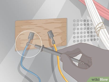
Credit: wikihow.com
Conclusion
Testing a wire is mostly about using the right mode, touching the right points, and reading the result the right way. Once you understand the difference between continuity, resistance, and voltage, the process becomes much easier.
The main idea behind How to Test a Wire With a Multimeter is simple: check the wire safely, isolate the path, and look for stable readings. If the result changes when you wiggle the wire, or if the reading is open when it should be closed, you have found a real fault.
Work slowly, confirm the meter is working, and test sections one at a time. That approach gives you clear answers and keeps you from replacing parts that are not actually bad.
If the wire checks out, the fault may be in the power source or control side instead. For a wall circuit, see how to test AC voltage with a multimeter. For a vehicle or battery-powered circuit, see how to test DC voltage with a multimeter so you can keep tracing the problem logically.
Safety note: Continuity and resistance tests must be done on a de-energized wire. If the circuit is live, switch to voltage mode instead of ohms or continuity mode.
FAQs
1. What setting should I use to test a wire with a multimeter?
Use continuity mode for a quick pass-or-fail check. If your meter does not have continuity, use the lowest ohms setting. Use voltage mode only when the circuit is powered and you want to check for live power.
2. Should a good wire always beep on a multimeter?
Usually yes in continuity mode, but not always. Very long wires or wires with some extra resistance may still be acceptable even if the beep is weak or delayed. Always look at the numeric reading too.
3. Can I test a wire without removing it from the circuit?
Sometimes, yes. But other parts of the circuit can affect the reading. If you want to test the wire alone, disconnect at least one end so the meter is not reading through switches, loads, or parallel paths.
4. Why does my wire show continuity but still not work?
The wire may have partial damage, corrosion, or too much resistance under load. The problem may also be in the connector, ground, switch, fuse, or the device itself. A continuity beep does not always mean the wire is perfect.
5. What if the multimeter shows OL or infinite resistance?
That usually means the circuit is open. The wire may be broken, disconnected, or not making contact at one of the probe points. Check both ends, inspect connectors, and test smaller sections to find the exact fault.