If a solenoid is not working, a multimeter can tell you fast whether the problem is electrical, mechanical, or both. How to Test a Solenoid With a Multimeter is a simple skill, and it can save you from replacing a part that is still good.
The key is to check the coil, the voltage supply, and the switching signal in the right order. With a few basic tests, you can spot an open coil, a shorted coil, weak power, or bad ground before you guess and waste time.
This guide walks through the process step by step, with clear settings, simple readings, and practical troubleshooting tips. You will also learn the common mistakes people make, what numbers matter, and when a solenoid should be replaced instead of repaired.
What a solenoid does and why the test matters
A solenoid is an electromagnetic switch. When power reaches the coil inside it, the coil creates a magnetic field that moves a plunger, piston, or internal contact. That movement can open a valve, engage a starter, lock a door, or control fluid or air flow.
Because the part has both electrical and mechanical pieces, a solenoid can fail in more than one way. The coil may burn out, the plunger may stick, the contacts may wear out, or the power feed may be weak even when the solenoid itself is fine.
This is why a multimeter test matters. It helps you separate a bad solenoid from a wiring problem, a blown fuse, or a weak battery. That can prevent unnecessary replacement and make diagnosis much faster.
One thing many beginners miss is that a solenoid can click and still be bad. The click only means the coil is moving something. It does not prove the contacts are passing current or that the plunger is moving far enough.
Common solenoid types you may test
Different machines use different solenoids, but the testing logic is similar. You may see starter solenoids, fuel shutoff solenoids, valve solenoids, transmission solenoids, or relay-style solenoids in cars, lawn equipment, appliances, and industrial machines.
Some solenoids use two heavy terminals and two small control terminals. Others use a single coil with one side grounded through the body. A few are pulse-controlled and may not behave like a simple on/off part. Always identify the type before testing.
If you are unsure about the exact part, check the official electrical safety guidance before working on powered equipment. Even low-voltage systems can create shock or burn hazards when tools slip or wiring is damaged.
Tools, safety steps, and what you need before testing
You do not need a large tool kit for this job. In most cases, a digital multimeter, basic hand tools, and access to the solenoid terminals are enough. If the part is built into a machine, removing a cover or panel may be necessary first.
Before you start, turn the machine off and disconnect power when possible. For vehicle or equipment systems, remove the key and follow lockout steps if the machine has them. If the solenoid is part of a battery-powered circuit, disconnect the battery negative terminal before resistance testing.
That last step matters because a multimeter in ohms mode sends a tiny current through the coil. If the circuit is live, the meter reading may be wrong, and you can also damage the meter or the control module.
What you need
- Digital multimeter with resistance, continuity, and DC voltage settings
- Basic hand tools for removing covers, connectors, or mounting hardware
- Needle probes or test leads for reaching small terminals
- Battery or power source access if you need live voltage testing
- Work gloves and eye protection when testing on equipment with moving parts
Set the meter to the correct mode before each test. Resistance uses ohms, usually shown as Ω. Voltage is often measured in DC volts, shown as V with a straight line symbol. Continuity is usually the sound or low-resistance test mode on many meters.
Here are the most useful readings to keep in mind: many 12-volt solenoid coils read somewhere between 5 and 20 ohms, but the exact range depends on the design. Large starter solenoids, fuel shutoff units, and small valve solenoids can vary a lot, so the spec sheet or manual is the best reference when available.
How to test a solenoid with a multimeter step by step
The best way to test a solenoid is to start with a resistance check, then verify voltage supply, and finally confirm that the solenoid is actually switching under power. That order helps you find the fault faster and keeps you from chasing the wrong problem.
1. Identify the terminals
Look at the solenoid and find the coil terminals, power terminals, and ground points if present. Many solenoids have two small terminals for the coil and two larger terminals for the load side. Some have a metal case that serves as the ground.
If the terminals are labeled, note them before you remove anything. Labels such as BAT, LOAD, S, IGN, or GND can tell you what each side does. If the label is not clear, check the machine diagram or service manual.
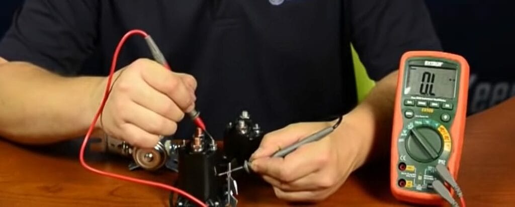
2. Test the coil resistance
Set the multimeter to resistance mode, usually the lowest ohms range. Disconnect the solenoid from power so you are measuring only the coil, not the whole circuit. Place one probe on each coil terminal, or on the coil terminal and ground if the solenoid uses a grounded case.
A good coil usually shows a steady reading instead of infinite resistance or nearly zero ohms. OL or no movement on the meter often means an open coil. A reading close to 0 ohms may mean a shorted coil, which can draw too much current and overheat.
One subtle point: a very slight fluctuation in reading is normal if the probes are not making solid contact. But if the reading jumps all over the place, the terminal may be corroded, loose, or dirty. Clean the contact point and test again before calling the solenoid bad.
3. Check for continuity
If your meter has continuity mode, use it as a quick follow-up test. Continuity confirms that current can pass through the coil, but it does not tell you whether the coil resistance is correct. A buzzer alone is not enough for final diagnosis.
This test is useful when the resistance value is very low and hard to read. You should still compare the result to the expected resistance range when possible. If the meter shows no continuity, the coil is open and the solenoid will not energize.
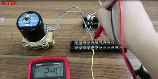
4. Measure supply voltage at the control side
Reconnect power if the next step requires live testing, and set the meter to DC volts. Place the black probe on a good ground and the red probe on the control terminal that should receive power when the solenoid is commanded on. Activate the switch, key, relay, or control signal.
You should see a voltage reading close to the system voltage. For a 12-volt system, that usually means something near 12 volts to 14 volts depending on charging state. For a 24-volt system, you may see roughly 24 to 28 volts while charging.
If the voltage is low, the problem may be upstream of the solenoid. A weak battery, corroded connector, bad switch, damaged wire, or failing relay can all keep the solenoid from pulling in, even if the coil is fine.
5. Test voltage drop under load
Voltage drop testing is one of the most useful checks, and many beginners skip it. A circuit may show voltage with no load, but collapse when the solenoid tries to draw current. That means the meter can say “power is present” even though the solenoid cannot actually work.
Measure voltage across the power path while the solenoid is engaged. If you see a large drop across a wire, connector, or switch, that component is creating too much resistance. In a healthy circuit, the drop should stay low. On many 12-volt systems, a drop above about 0.5 volts on a single connection is a clue that something needs cleaning or repair.
6. Confirm the solenoid switches properly
If the coil resistance is good and the proper voltage reaches the terminals, the last step is to confirm movement and output. Listen for a solid click, then check whether the load side becomes connected or energized. On some parts, you can test continuity across the main terminals before and after activation.
A solenoid may click but still fail to pass current through the main contacts. This is common in starter solenoids and high-current relays, where the internal contacts can burn or pit over time. In that case, the coil works but the load side does not.
If the solenoid controls a valve, you may also need to confirm physical movement. Sometimes the electrical side is good, but the plunger is stuck from rust, dirt, or debris. A meter will not show that mechanical problem by itself.
7. Compare your reading to expected values
After testing, compare what you found with the expected range for that specific solenoid. If the coil resistance is way outside normal, the solenoid is likely faulty. If resistance is good but voltage is missing, the wiring or control side is the problem.
The table below shows a simple way to read the results.
| Test result | What it usually means | Likely next step |
|---|---|---|
| OL or infinite resistance | Open coil | Replace the solenoid |
| Near 0 ohms | Shorted coil | Replace the solenoid and check for overload causes |
| Correct resistance, no voltage | Power or control fault | Trace fuse, switch, relay, or wiring |
| Voltage present, no movement | Mechanical jam or weak coil | Inspect plunger and solenoid body |
| Clicks but no output | Worn internal contacts | Replace the solenoid |
Reading the results without guessing
Good diagnosis is more than getting a number. You need to decide what the number means in context. That is where many repairs go wrong, because people replace the solenoid when the real fault is a corroded connector or a weak control signal.
If the resistance test fails, the solenoid itself is usually the problem. If the resistance test passes, but the coil does not energize, the issue is likely voltage supply, ground, or control. If the coil energizes and the output still fails, the internal contacts or mechanical parts may be worn.
One non-obvious clue is heat. A solenoid that runs hot very quickly often has excess current draw, poor grounding, or a partial short in the coil. A warm housing is not always bad, but a very hot unit after only a short activation is a warning sign.
Credit: atosolenoidvalves.com
Credit: toolsweek.com
Common mistakes to avoid
- Testing resistance while the circuit is still powered
- Checking the wrong terminals and calling the part bad
- Assuming a click means the solenoid is working fully
- Ignoring ground quality on metal-case solenoids
- Using continuity alone without checking actual resistance
- Forgetting that a bad connector can mimic a bad solenoid
Another mistake is not comparing readings under load. A circuit can look fine with the key on and still fail when the solenoid draws current. That is why voltage drop testing is so useful on stubborn faults.
When the solenoid is fine but the system still fails
Sometimes the solenoid tests good and the machine still does not work. In that case, focus on the rest of the circuit: fuse, relay, switch, controller, battery, ground path, and load side. A solenoid is only one link in the chain.
If you are testing a starter circuit, for example, the battery must have enough voltage under load. A battery can show 12.6 volts at rest and still fail when asked to deliver current. That is why system-level testing matters.
If you are testing a fuel or valve solenoid, weak supply voltage may cause partial movement. Partial movement can create intermittent symptoms that look like a bad part, especially when the fault only appears when the machine gets hot.
Special cases: starter solenoids, valve solenoids, and grounded-case designs
Not every solenoid is wired the same way. Starter solenoids often use heavy current contacts plus a smaller control coil. Valve solenoids may use one coil with a body ground. Relay-style units may have a diode or suppression device built in, which can affect meter readings.
Grounded-case solenoids deserve special attention. If the metal housing is part of the circuit, paint, rust, or a loose mounting bolt can stop it from working. In those cases, resistance from the terminal to the case should usually match the intended design, not read as an open circuit.
Some modern solenoids also include a flyback diode to protect electronics from voltage spikes. A diode can make one direction of continuity read differently than the other. If your readings seem odd, do not force a conclusion before checking the part design.
If you need factory specifications for a machine or engine, use the official manual or support page from the manufacturer. That is the best way to confirm coil resistance, terminal layout, and any special testing steps for that exact part.
What to do after the test
Once you know whether the solenoid is good or bad, move to the next likely fault. If the solenoid failed resistance testing, replace it and inspect the connector for heat damage or corrosion. If the solenoid passed, repair the supply circuit first.
Clean any dirty terminals, tighten loose connections, and check for rubbed wires near moving parts. On many machines, a failed solenoid is actually the result of another problem that caused the solenoid to overwork. Fixing only the part without finding the root cause can lead to repeat failure.
It also helps to document your readings. Write down the resistance value, voltage at the terminal, and any visible damage. That record makes it easier to compare the new part after installation and can help if the machine acts up again later.
If the solenoid is part of a safety-critical system and the test results are unclear, stop and get professional help. Electrical systems can behave unpredictably when wiring is damaged, and forcing the issue can create a larger repair.
Simple diagnosis flow you can follow every time
- Identify the solenoid type and terminals.
- Disconnect power before resistance testing.
- Check coil resistance with a multimeter.
- Confirm continuity only as a quick support test.
- Restore power and measure control-side voltage.
- Check voltage drop if the reading looks weak.
- Verify that the solenoid clicks and switches load current.
- Replace the part only if the solenoid itself fails the test.
This order keeps the diagnosis clean. It starts with the easiest test that tells you the most, then moves toward live checks only when needed. That saves time and avoids accidental damage.
If you are learning the process, practice on a known-good solenoid first. Seeing a healthy reading once makes it much easier to spot a bad one later.

Credit: reddit.com
Final take
How to Test a Solenoid With a Multimeter is really about checking three things in the right order: coil condition, power supply, and switching action. When you do those checks carefully, you can tell whether the solenoid is dead, weak, stuck, or only being blamed for a wiring problem.
The biggest win is avoiding guesswork. A few accurate readings can save time, reduce part swaps, and point you straight to the real fault. Once you learn the pattern, solenoid testing becomes one of the fastest troubleshooting jobs you can do.
If your solenoid is not activating, also check whether power is reaching it. These guides on how to test DC voltage with a multimeter and how to test a wire with a multimeter can help you rule out a weak feed, bad ground, or broken control wire.
Safety note: Disconnect system power before resistance or continuity tests. If you apply live voltage to confirm operation, use the correct rated voltage and keep clear of any moving parts.
Frequently Asked Questions
1. What setting should I use on my multimeter to test a solenoid?
Use resistance mode, usually shown as Ω, to test the coil first. Then use DC voltage mode to check the power supply. If your meter has continuity mode, you can use it as a quick extra check, but not as the only test.
2. What resistance should a good solenoid have?
It depends on the model, but many 12-volt solenoid coils read somewhere between 5 and 20 ohms. Some coils will be lower or higher. The best answer is always the value listed in the machine manual or manufacturer spec sheet.
3. Can a solenoid click and still be bad?
Yes. A click only means the coil is moving the plunger or internal mechanism. The contacts may still be worn, burned, or unable to pass current, so the solenoid can click and still fail to do its job.
4. How do I know if the problem is the solenoid or the wiring?
If the coil resistance is good but no voltage reaches the control terminal, the wiring, fuse, relay, switch, or controller is likely at fault. If voltage is present but the solenoid still does not work, the solenoid or its ground path is more likely the problem.
5. Should I replace a solenoid if the meter shows no continuity?
Yes, in most cases. No continuity usually means the coil is open, so the solenoid cannot energize. Before replacing it, make sure the meter is connected correctly and the part is fully disconnected from power.