
Are you wondering if your motor is working properly or if it needs repair? Knowing how to test a motor with a multimeter can save you time, money, and frustration.
Whether it's a single-phase fan motor or a three-phase industrial motor, a multimeter can quickly screen for open windings, obvious shorts, and large resistance imbalance. A standard digital multimeter does not fully prove motor insulation health; for insulation-to-ground condition, use the manufacturer's manual/nameplate limits and a proper insulation resistance tester such as a megohmmeter.
Use this guide as a safe first check after the motor is fully disconnected from power. If readings are unclear, the motor is high-voltage/industrial, or insulation resistance is in question, stop and have a qualified technician test it with the right equipment.
As an Amazon Associate, I earn from qualifying purchases. This helps support the site at no extra cost to you.
Motor testing is easier with a dependable digital meter that can read resistance clearly. If your meter jumps around or lacks basic protection, see our best digital multimeters guide before doing more electrical troubleshooting.
Prepare The Motor And Multimeter
Preparing the motor and multimeter is the first step to test a motor correctly. If you do not have a reliable multimeter, we recommend the AstroAI Digital Multimeter for accurate resistance and continuity testing. This step ensures your safety and accuracy in readings. Proper preparation avoids damage to the motor and the multimeter. Follow each instruction carefully for the best results.

Disconnect Power Safely
Before testing winding resistance, isolate the motor from every supply and prevent accidental restart. For fixed equipment, a qualified person should follow the required lockout/tagout procedure and verify absence of voltage using properly rated test equipment. Merely switching off a breaker or relying on a non-contact detector is not adequate proof of de-energization. Read our voltage-tester guide for general meter use, and follow the motor maker’s stored-energy and capacitor-discharge instructions.
Remove any connected wires or cables from the motor terminals. Keep the motor isolated to get accurate resistance readings. Never test the motor while it is connected to power.
Set Multimeter To Ohms
Turn on your multimeter and set it to the resistance mode, often marked with the Greek letter omega (?). This mode measures electrical resistance inside the motor windings. Use the lowest ohm range for precise readings if your multimeter has manual settings.
Inspect the multimeter and leads before testing. Connect the black lead to COM and the red lead to the V/Ω jack, not the current (A) jack. Short the probe tips together first to check lead resistance, and use the meter’s REL/zero function if available for low-ohm measurements. Properly secured alligator clip test leads may improve contact with isolated motor terminals.
Test Motor Windings For Continuity
Continuity and winding-resistance checks help identify open circuits, disconnected leads and gross faults in a de-energized, isolated motor. Continuity alone does not prove that the winding insulation, individual turns or mechanical parts are healthy; further tests may be needed.
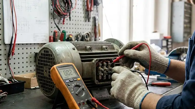
Using a multimeter to check continuity is simple and effective. It gives clear readings that show if the motor windings are healthy or damaged. Follow the steps carefully to get accurate results.
Check Resistance Between Terminals
Set the multimeter to ohms (Ω) and measure between the isolated winding terminals identified by the motor wiring diagram. Account for resistance of the test leads, and compare the result with the maker’s specifications or similar windings. A low steady value can be normal and does not by itself confirm or rule out shorted turns.
An OL reading across the correct isolated winding terminals may indicate an open winding, disconnected lead or a wrong meter range. Verify the motor wiring diagram first. Very low resistance alone does not prove a short; many motor windings are naturally low resistance, and test leads affect the reading. Compare with the motor manufacturer’s specifications and comparable windings.
Test each pair of terminals this way. Note the readings for all windings to compare.
Identify Open And Short Circuits
An open circuit means the motor winding is broken inside. The multimeter shows no continuity, and the resistance reads very high or infinite. This fault prevents the motor from running.
A winding can develop shorted turns or internal faults even when its resistance appears close to normal on a handheld multimeter. Resistance measurements can reveal gross shorts, opens or imbalances, but suspected inter-turn faults may require specialist motor test equipment.
With the motor safely isolated and de-energized, a multimeter reading from a winding terminal to the metal frame can screen for an obvious low-resistance ground fault. An OL reading does not prove the motor’s insulation is healthy, and not every finite reading indicates a direct short. If insulation condition is in question, a qualified technician should perform an insulation-resistance test using the correct equipment and motor specifications.
Check For Shorts To Ground
Checking for shorts to ground is a critical step when testing a motor with a multimeter. This process ensures the motor windings do not have unintended contact with the motor frame or housing. Such shorts can cause motor failure or electrical hazards.
With a multimeter, you can screen for a direct short between a motor terminal and the metal frame. This is useful, but it is not the same as an insulation resistance test. Insulation problems caused by moisture, dirt, age, or cracked insulation may require a megohmmeter/insulation tester and the limits from the motor manual or nameplate.
Test Resistance To Motor Frame
First, set your multimeter to the ohms setting. Touch one probe to a motor terminal. Place the other probe on the clean metal frame of the motor.
Look for the resistance reading on the multimeter. A very high resistance or “OL” reading usually means the meter does not see a direct short from that terminal to the frame. It does not prove the insulation is healthy under operating voltage.
A low resistance reading can indicate a winding-to-frame short, contamination, moisture, or damaged insulation. Do not energize the motor until the cause is found. Repeat this test for each motor terminal, then confirm questionable results with the manufacturer's procedure or an insulation resistance tester.
Interpret Ground Test Results
If the multimeter shows “OL” or no continuity, it only means the meter did not detect a direct short to ground. Treat that as a quick screening result, not a final safety certificate. Insulation resistance testing is the proper next step when the motor has been wet, overheated, stored for a long time, or used in critical equipment.
If the meter shows low resistance or continuity to the frame, the motor may have a ground fault or insulation failure. Do not use the motor until it is inspected, dried/cleaned if appropriate, repaired, or replaced by a qualified person.
Testing for shorts to ground helps catch obvious faults, but safe motor operation also depends on insulation condition, supply voltage, current draw, bearings, load, and the motor's rated limits. Always disconnect power and verify absence of voltage before resistance tests.
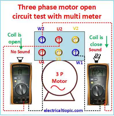
Credit: electricaltopic.com
Test Single-phase Motors
Testing single-phase motors with a multimeter helps find motor problems fast. These motors have two windings: start and run. Knowing which winding is which makes testing easier. Checking their resistance values shows if the motor is good or damaged. Follow clear steps for accurate results.
Identify Start And Run Windings
Many capacitor-start, split-phase and permanent-split-capacitor single-phase induction motors have main and auxiliary windings, but connections differ by model. Consult the manufacturer’s wiring diagram to identify each winding; do not infer lead identification solely from wire color or a presumed resistance difference. Disconnect any external capacitor or control components as instructed and have stored energy dealt with safely.
Measure Resistance Values
With the motor isolated, absence of voltage verified and any connected capacitor handled according to the manufacturer’s instructions, use ohms mode across the correct winding terminals. The main and auxiliary winding resistances depend on motor design; statements such as “run winding is usually below one ohm” are not universal limits. Compare with the maker’s specifications, account for meter-lead resistance, and refer suspected insulation defects for proper insulation testing.
Test Three-phase Motors
Testing three-phase motors with a multimeter helps find electrical problems fast. These motors have three windings, each connected to a phase. Checking each winding ensures the motor works properly and safely.
Follow simple steps to measure resistance and spot issues like shorts or open circuits. Use your multimeter to compare readings and confirm the motor's condition. This process helps avoid costly repairs or replacements.
Check Each Winding Pair
Set your multimeter to the ohms (?) setting. Test resistance between each pair of motor terminals. These pairs are usually labeled U, V, and W. Measure U to V, V to W, and W to U.
Record the phase-to-phase resistance readings and note the winding temperature, terminal links and test setup. A normal motor may have a resistance so low that a handheld meter displays nearly zero; that display alone does not confirm a short. An OL reading across an expected connected winding path requires further investigation. Compare against manufacturer data or previous measurements, using a suitable low-resistance tester when necessary.
Compare Resistance Readings
Compare the three resistance readings from the winding pairs. They should be close to each other. Small differences are normal due to manufacturing variations. Large differences mean one winding may be damaged.
Phase-to-phase resistance readings of comparable windings are expected to be close when the motor connections and temperature are equivalent. A significant mismatch can indicate faulty connections or winding damage; first check the motor’s star/delta link configuration and compare the readings with manufacturer specifications before deciding on repair or replacement.
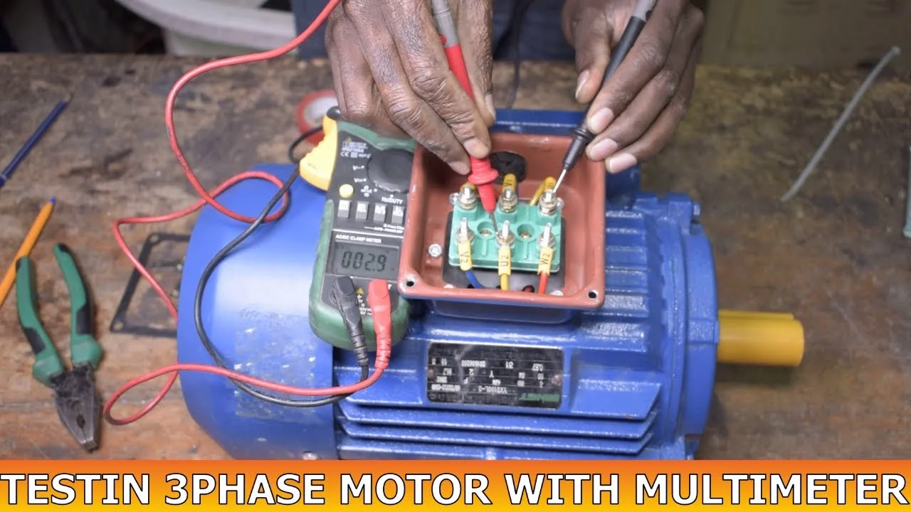
Credit: www.youtube.com
Interpret Multimeter Readings
Interpreting multimeter readings is crucial for testing motors accurately. Understanding these readings helps identify motor health and issues quickly. This section explains how to read resistance values and spot common faults.
Recognize Normal Resistance Ranges
There is no universal normal winding resistance, such as 1–100 ohms, for every electric motor. Values vary by motor design, size, voltage, connection and temperature, and some healthy windings measure well below one ohm. A standard handheld meter may not accurately resolve such low values; consult the motor manufacturer’s specifications and use suitable low-resistance test equipment where needed.
Check your motor's manual for exact numbers. Consistent readings across all winding pairs indicate normal condition. Slight differences are normal but should not be very large.
Measure between the winding terminals identified in the motor’s wiring diagram after safely disconnecting power and isolating external components. Compare equivalent measurements and account for test-lead resistance. A near-zero reading on its own does not prove a winding fault or shorted turns.
Detect Fault Indicators
OL across an expected winding path can indicate an open winding, disconnected connection, or incorrect range or test points. Near-zero resistance may be normal in a low-resistance winding; compare the result with the motor’s specified resistance and use appropriate equipment before diagnosing a short.
A standard multimeter can screen for an obvious winding-to-frame short on an isolated, de-energized motor. Persistent very low resistance is a warning that needs investigation, but a finite reading does not always mean an insulation fault, and OL does not prove safe insulation. Insulation resistance should be checked with an appropriate tester and the manufacturer’s test criteria by a qualified person.
Uneven resistance across windings or unexpected values warn of internal damage. Identifying these signs early prevents motor failure and saves repair costs.
Troubleshoot Common Motor Issues
Troubleshooting common motor problems starts with identifying the exact issue. Motors often face electrical faults that stop them from working correctly. Using a multimeter helps find these problems quickly. Two frequent issues are open circuits and short circuits. Both affect motor performance and safety.
Address Open Circuits
Open circuits occur when the electrical path inside the motor breaks. The multimeter set to the ohms (?) mode checks this easily. Touch the probes to the motor winding terminals. A reading of “OL” or infinite resistance means the circuit is open. This means no current flows through the winding. Open circuits stop the motor from running.
Check each winding separately. Open circuits can happen from broken wires or bad connections. Repair or replace damaged parts to fix the issue. Always disconnect power before testing to avoid shocks.
Handle Short Circuits
Shorted turns can lead to overheating and motor failure, but an ordinary ohmmeter may not detect small changes in winding resistance. A very low or near-zero display can also reflect a normal winding or lead resistance. Confirm the test setup, compare phase readings against motor data and refer suspected internal faults for specialist testing.
After safely isolating the motor, a low-resistance path between an isolated winding and its metal frame is a warning sign. However, a reading other than OL does not automatically confirm a short, nor does OL certify insulation safety. Have insulation condition assessed with an appropriate insulation-resistance test if required.
Next Steps After Testing
After testing a motor with a multimeter, it is important to know what to do next. This step determines the motor's future use and ensures safety. The test results guide whether the motor needs repair or replacement. Proper handling after testing also protects you and the motor from harm.
Decide On Repair Or Replacement
Check the test readings carefully. If the motor shows an open circuit or short circuit, it may be faulty. Minor issues like dirty contacts or loose wires can be repaired. Severe damage such as burnt windings or broken parts often means replacement is needed. Consider the motor's age and cost of repair. Sometimes buying a new motor is more cost-effective.
Consult a professional if unsure about the motor's condition. Proper diagnosis saves time and money. Keep your motor's manual handy for specific guidelines. Use the test results to explain the problem clearly.
Safety Tips For Motor Handling
Always disconnect power before touching the motor. Use insulated tools to avoid electric shock. Wear insulated electrician gloves and safety eyewear during handling. Avoid working on the motor in wet or damp places. Keep the workspace clean to prevent accidents.
Store the motor in a dry, cool area if not in use. Follow manufacturer instructions for safe handling. Dispose of damaged motors properly to protect the environment. Safety is key to prevent injury and damage.
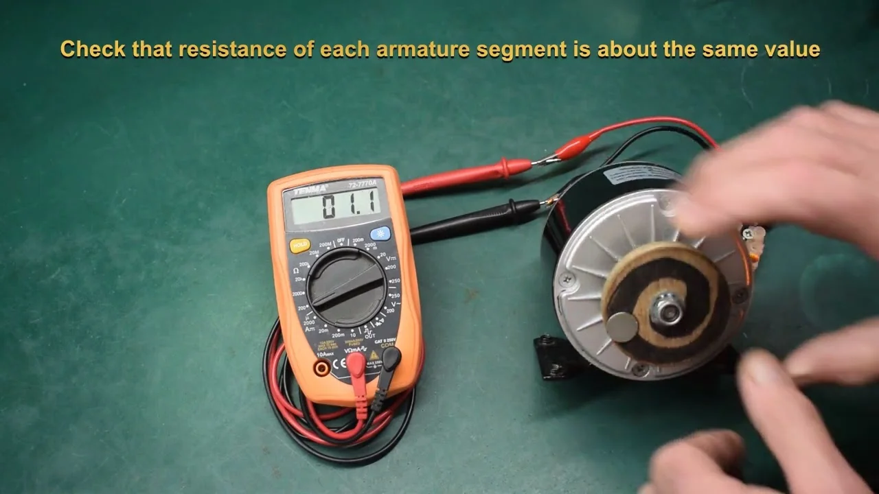
Credit: www.youtube.com
Authoritative External References
For further verification and technical guidance, review these authoritative external resources:
- Fluke – Test tools for electrical motors
- EASA – Performing an insulation resistance test
- OSHA – Electrical Safety Overview
- Fluke: Resistance measurements, lead resistance and disconnected circuits
- Megger: Motor winding resistance, turn faults and insulation testing
- OSHA 1910.333: Safe isolation and verification of de-energized circuits
- Oriental Motor: Capacitors and single-phase motor configurations
Related testing guides: Motor problems often involve connected electrical parts too. You may also need to test a capacitor with a multimeter or test a battery with a multimeter before replacing parts.
Frequently Asked Questions
How To Test If A Motor Is Bad With A Multimeter?
Disconnect power, verify the circuit is de-energized, then measure winding resistance and compare the readings with the motor manual or nameplate data. OL can indicate an open winding, and near-zero resistance can indicate a short, but exact values vary by motor. A multimeter frame test only screens for direct shorts; use a megohmmeter for insulation resistance.
How To Test A 3 Phase Motor With A Multimeter?
Disconnect power, verify zero voltage, then measure resistance between each phase. The three winding readings should be close to each other; a large mismatch, OL, or near-zero reading needs further diagnosis. Also screen each terminal to the motor frame, but remember that a normal DMM reading does not replace an insulation resistance test for ground insulation.
How Many Ohms Should An Electric Motor Have?
There is no single normal ohm value for every electric motor. Winding resistance depends on motor type, horsepower, voltage, winding design, temperature, and lead configuration. Compare readings with the manufacturer's data when available; for three-phase motors, similar phase-to-phase readings are often more useful than one generic number. Always disconnect power before testing.
How To Tell If A Motor Has Bad Windings?
Test motor windings with a multimeter set to ohms. OL may indicate an open winding, and near-zero resistance may indicate a short, but compare against the motor's rated design before calling it failed. Any low-resistance path to the frame needs professional follow-up, and insulation resistance requires a megohmmeter.
How Do I Test Motor Windings With A Multimeter?
Set your multimeter to ohms and check resistance between winding terminals. Compare the readings with the motor manual or with matching phases on the same motor; OL, near-zero resistance, or a large imbalance suggests a problem.
What Does A Zero Resistance Reading Mean On A Motor?
Near-zero resistance can indicate a shorted winding or the wrong test points. Recheck the lead identification and manual first; if the reading stays near zero, do not run the motor until it is inspected.
Conclusion
Testing a motor with a multimeter helps find obvious electrical problems fast. Always turn off power and verify zero voltage before starting any resistance test. Check each winding for opens, shorts, and imbalance, then screen terminals to the motor frame.
A multimeter is a first diagnostic tool, not a complete motor health test. Faulty or questionable motors may need insulation resistance testing, current checks, bearing inspection, repair, or replacement before they are safe to return to service.