
To test a ground path with a multimeter, first identify what you are testing. For a de-energized vehicle or low-voltage circuit, continuity or low-ohms testing can reveal an open or high-resistance ground path. A handheld multimeter cannot certify a building grounding-electrode system; that requires the correct test method and equipment.
For low-voltage automotive or electronics work, a continuity or resistance check can reveal loose, corroded, or broken ground paths. For household receptacles, panels, or any energized circuit, use the right tester, follow local code, and call a qualified electrician if you are unsure. Do not use resistance or continuity mode on a live circuit.
This guide focuses on safe multimeter screening: confirm power is off before resistance tests, compare readings against a known reference, and treat questionable results as a reason for proper electrical inspection.
As an Amazon Associate, I earn from qualifying purchases. This helps support the site at no extra cost to you.
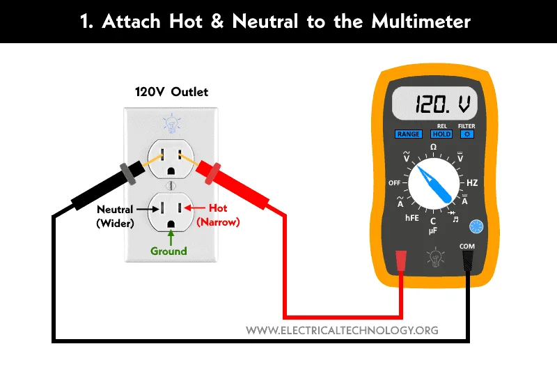
Credit: www.electricaltechnology.org
For repeated ground and current checks, some users may also need a clamp-style meter. Our best clamp meters guide explains when a clamp meter is more practical than a standard handheld multimeter.
Essential Tools Needed
Testing ground with a multimeter requires some basic tools. These tools help ensure accurate readings and safety during the process. Having the right equipment makes the task easier and faster.
This section covers the essential tools needed for ground testing. Each tool plays a specific role in the process. Let's explore what you need before you start.
Multimeter
A multimeter is the main tool for testing ground connections. It measures voltage, resistance, and continuity. Choose a digital multimeter for clear, easy-to-read results. We recommend the AstroAI Digital Multimeter for reliable ground testing. Make sure it has a continuity test mode for checking ground paths.
Test Leads
Test leads connect the multimeter to the circuit or ground point. They should be in good condition with no broken wires. Use insulated leads to avoid electric shocks. Some multimeters come with test leads, but quality matters. For better contact during ground testing, upgrade to alligator clip test leads for hands-free connections.
Insulated Gloves
Safety is important when working with electrical systems. Insulated electrician gloves and insulated tools can reduce risk only when they are properly rated and used correctly. They are not a substitute for turning power off, verifying zero voltage, and getting professional help for live household wiring or panel work.
Wire Stripper
A wire stripper is only needed when a qualified person is installing or repairing an isolated conductor, not for a normal ground-continuity check. For testing, use existing approved test points and avoid cutting or stripping insulation to make probe contact. Do not alter household protective-earth wiring yourself.
Screwdriver
A screwdriver may be used for accessible covers on disconnected low-voltage equipment when the manufacturer’s instructions allow it. Do not open household electrical panels, receptacle boxes or other potentially energized enclosures merely to look for a ground point; that work requires an appropriately qualified electrician and verified safe isolation.
Preparing Your Multimeter
Preparing your multimeter is the first step to accurately test a ground connection. Proper setup ensures reliable readings and prevents damage to the device or circuit. Follow simple steps to get your multimeter ready before testing.
Check The Multimeter Battery
Start by verifying the battery level. A low battery can cause incorrect readings. Replace the battery if the display is dim or the multimeter does not turn on. This step saves time and frustration.
Select The Correct Measurement Mode
Turn the dial to the right setting. For ground testing, use the resistance (ohms) or continuity mode. Continuity mode helps detect if the circuit is complete by beeping. Resistance mode shows the exact resistance value.
Inspect The Test Leads
Look over the test leads for damage or wear. Cracked insulation or broken wires may affect the accuracy. Replace faulty leads to ensure safety and correct results.
Calibrate The Multimeter
Factory calibration and correcting for test-lead resistance are different tasks. For a short, de-energized ground or bond check, first touch the probes together, note their resistance, and use REL/zero if the meter supports it; otherwise account for the lead reading when interpreting results. Follow the meter manufacturer’s calibration schedule separately.
Setting Multimeter For Ground Testing
Setting your multimeter correctly is key to test ground connections accurately. The right setup helps you find faults fast. It also protects your multimeter from damage. Follow simple steps to prepare your device for ground testing.
Start by switching on the multimeter. Then, choose the right mode for your test. This ensures you get clear and correct readings every time.
Choosing The Correct Measurement Mode
For an isolated, verified de-energized low-voltage path, resistance mode measures the electrical resistance between the probe points; continuity mode signals when that resistance is below the meter’s beep threshold. Neither setting measures how much fault current a building’s protective grounding can carry, and neither should be used on an energized circuit.
Setting The Range On Your Multimeter
With power safely removed, select resistance (Ω) or continuity mode. An auto-ranging meter chooses its range automatically; for a manual-ranging meter, follow its instructions and choose a suitable low-ohms range for a short bond or wire. Subtract or zero test-lead resistance where needed. Never use the ohms function on a live circuit.
Preparing The Test Leads
Plug the black lead into the common (COM) jack. Insert the red lead into the resistance or continuity jack. Check the leads for damage before use. Good condition leads ensure reliable readings and safety.
Calibrating The Multimeter
Touch the test leads together before testing. The resistance display may show the leads’ own resistance rather than exactly zero, and continuity may beep according to the meter’s threshold. If supported, use REL/zero to compensate for lead resistance. This is a basic lead check, not a calibration of the multimeter or proof of the tested grounding path’s safety.
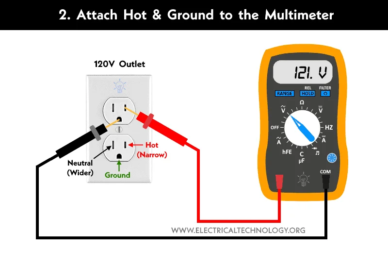
Credit: www.electricaltechnology.org
Locating The Ground Point
Locating the ground point is the first step when testing ground with a multimeter. The ground point acts as the reference for all electrical measurements. Finding it correctly ensures accurate results and safe testing.
For most conventional 12V negative-ground vehicles, the chassis and designated ground straps form a return path to the battery’s negative terminal; a vehicle does not need an earth connection for that circuit to work. Household protective-earth conductors and grounding electrodes serve different purposes. Identify the correct spot carefully using the device’s wiring diagram rather than treating any metal surface as a verified ground reference.
Check The Device Manual For Ground Location
Start by reviewing the device or vehicle manual. Most manuals show the exact ground points. This saves time and avoids guesswork. Manuals often indicate ground symbols and wiring diagrams.
Look For Clean Metal Surfaces
Ground points usually appear as bare metal surfaces. Remove any paint or rust to find a good connection spot. These surfaces should be free of dirt and corrosion for reliable testing.
Identify Common Ground Symbols
Symbols help locate ground easily. A line with three horizontal lines below is a common ground sign. Spot these on circuit boards or near connectors to find ground points quickly.
Use A Multimeter To Confirm Ground
On a safely isolated, de-energized low-voltage device or vehicle circuit, use a documented ground reference to check continuity or resistance across the path. A low reading after accounting for probe and lead resistance suggests a connection between those points, but does not prove the entire ground path is reliable under load or that a building’s grounding system meets safety requirements.
Inspect For Loose Or Damaged Connections
On disconnected low-voltage equipment, visually inspect accessible grounding straps and terminals for corrosion, looseness or damaged conductors, then follow the manufacturer’s repair and torque specifications. Do not loosen, disconnect or repair household protective-earth, bonding or grounding-electrode connections yourself; have a qualified electrician diagnose those installations.
Measuring Resistance Of Ground Wire
Measuring resistance on a disconnected ground wire is a useful continuity check, but it does not prove the full grounding system can safely clear a fault. A low reading usually means the tested path is continuous; high resistance or no continuity can point to loose connections, corrosion, broken conductors, or the wrong reference point.
A basic multimeter reading gives useful clues, not a code certification. For building grounding, receptacle grounding, or grounding electrode systems, use the correct test method and a qualified electrician when the result affects safety.
Preparing Your Multimeter For Resistance Measurement
Start by turning off power to the circuit. Set your multimeter to the resistance (ohms) mode. Choose a low range if your meter is not auto-ranging. This prepares the tool for a correct reading.
Connecting The Multimeter To The Ground Wire
Attach one probe to the ground wire or grounding point and the other to a verified reference point for that device or circuit. Use the device manual, wiring diagram, or a known equipment grounding conductor rather than guessing. Make sure probes touch clean metal surfaces; avoid painted, rusty, or loose points.
Reading And Interpreting Resistance Values
Look at the multimeter screen for the resistance value. For a simple wire or chassis continuity check, the reading should be very low after subtracting the resistance of your test leads. Do not use one generic 5-ohm rule for every ground system; acceptable values depend on the equipment, circuit design, local code, and the test method. If the meter shows infinite resistance, the wire may be broken or your reference point may be wrong.
Troubleshooting High Resistance In Ground Wire
Inspect exposed, safely de-energized low-voltage ground terminals for corrosion, poor contact or broken conductors. Clean or repair only as the manufacturer specifies, and retest afterward. For building wiring or unknown-voltage equipment, do not brush, loosen or reterminate grounding components yourself; request electrician-level inspection.
Checking Continuity To Ground
Checking continuity to ground is a basic way to confirm that a disconnected ground path is not open. It helps find broken wires and loose connections, but it does not replace code-required grounding, GFCI protection, or professional testing for building wiring.
Using a multimeter, you can test continuity between the ground wire and a verified reference point. A beep or very low resistance suggests a continuous path between those two points only. It does not prove polarity, GFCI protection, or fault-clearing performance.
Preparing Your Multimeter For Continuity Testing
Set your multimeter to the continuity mode. This mode often has a symbol like a sound wave or diode. If your meter lacks this mode, set it to the lowest resistance (ohms) setting.
Ensure your multimeter leads are properly connected. Insert the black lead into the common (COM) port and the red lead into the voltage or ohms port.
Use the verified reference identified by the equipment or vehicle manufacturer’s wiring diagram, such as a designated chassis ground stud or battery-negative point in a compatible low-voltage vehicle circuit. Do not assume an arbitrary water pipe, ground rod, or bare metal surface is a safe or valid reference. Never open energized household equipment to find one.
Touch one multimeter lead to the ground point. Hold it steady to get a stable reading.
Testing Continuity Between Ground And Wire
Touch the other multimeter lead to the ground wire or terminal you want to test. The multimeter will beep or show a low resistance number if continuity exists.
A reading close to zero ohms suggests the tested ground path is continuous. You can apply similar careful probe-contact habits when you test a battery with a multimeter. A high reading or no beep may mean the ground is broken, disconnected, corroded, or referenced to the wrong point.
Interpreting Your Results
Continuous beeping or a low resistance value confirms continuity between the two points tested. It does not by itself prove that fault current can safely clear a breaker or that the installation meets code.
No sound or a high resistance reading indicates a problem or a poor reference point. Check for loose connections, corrosion, or damaged wires only after the circuit is de-energized; call a qualified electrician for household wiring faults.
Identifying Faulty Ground Connections
Identifying faulty ground connections is crucial for electrical safety and performance. A bad ground can cause equipment failure, electrical shocks, or erratic behavior. Testing ground connections with a multimeter helps find issues quickly. This ensures your system runs smoothly and safely.
Understanding The Role Of Ground Connections
In a vehicle, a designated chassis-ground path returns normal load current toward the battery; in building wiring, the equipment-grounding conductor and bonding system provide a low-impedance path for fault current back to its source so protective devices can operate. The earth electrode has a different role. A broken or high-impedance protective connection can create serious shock hazards; a simple multimeter continuity result does not certify its performance.
Signs Of A Faulty Ground Connection
Dim or flickering lights, erratic electronics, visibly corroded connections, overheating or repeated protective-device trips may suggest electrical faults, including a bad ground, but none identifies the cause by itself. In automotive low-voltage circuits, Fluke recommends diagnosing suspected ground restrictions with a voltage-drop test under the appropriate load; resistance testing alone can miss poor connections. Live household-wiring diagnosis should be performed by a qualified electrician.
Using A Multimeter To Check Ground Continuity
For a verified de-energized and appropriately isolated low-voltage circuit, place the probes between the ground conductor being checked and the specific reference identified in the equipment wiring diagram. A low-ohm reading suggests continuity between those points, while a high or OL reading may reflect a disconnected path, poor contact or wrong reference. Do not use a metal water pipe or ground rod as an assumed reference or mistake this check for an earth-electrode resistance test.
Inspecting Ground Connections Physically
Look for loose bolts, rust, or damaged wires at the ground point. Clean off any corrosion and tighten connections. Replace frayed or broken wires. A secure, clean connection improves electrical flow and safety.
Measuring Ground Resistance For Accuracy
Use the multimeter’s resistance setting to measure the ground resistance. For equipment-ground or chassis-ground continuity, a good path should measure very low resistance relative to the test leads. Earth-ground electrode resistance is a different measurement and normally requires a dedicated ground-resistance tester rather than a standard multimeter.
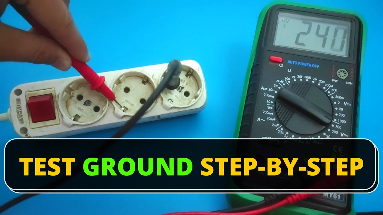
Credit: www.youtube.com
Tips For Accurate Readings
Accurate readings are essential when testing ground with a multimeter. Small mistakes can lead to wrong results and unsafe conditions. Follow simple tips to get precise measurements every time. These tips help avoid common errors and improve your testing process.
Use The Correct Multimeter Setting
Select the right mode on your multimeter. For ground testing, use the resistance (ohms) or continuity setting. This choice ensures the meter measures the connection properly. A wrong setting may give false readings or damage the device.
Check The Probes And Connections
Inspect the test probes before starting. This is as important when you test a motor with a multimeter. Clean and firm probe tips give better contact with metal surfaces. Loose or dirty connections cause unstable readings. Hold the probes steady during measurement to avoid fluctuations.
Test On Clean Metal Surfaces
When checking a documented ground test point on safely isolated low-voltage equipment, make probe contact with the designated conductive surface; paint, dirt or corrosion can distort a resistance reading. Do not scrape away protective finishes or alter installed building grounding connections without manufacturer guidance. The same attention to clean surfaces applies when you prepare painted metal surfaces, although surface preparation alone cannot certify grounding safety.
Keep The Multimeter Steady
Hold the multimeter and probes still while testing. Movement can change the reading or break contact. Place the meter on a flat surface for stability. Take your time to get a stable and consistent reading.
Verify The Ground Reference Point
Choose a known good ground point as a reference. This helps compare and confirm your reading. Check multiple points if needed to find the best ground. A proper reference ensures the test results are reliable.
Authoritative External References
For further verification and technical guidance, review these authoritative external resources:
- OSHA – Electrical Safety Overview
- OSHA – Ground-Fault Circuit Interrupters
- OSHA 1910.304 – Wiring design and protection
- Fluke – How to Measure Resistance with a Digital Multimeter
- NFPA – 5 ways to check GFCIs
- Fluke – Automotive Ground-Circuit Voltage Drop Troubleshooting
- Fluke – Ground Electrode Impedance Testing: Special Equipment and Methods
- OSHA – Verify De-energized Condition Before Electrical Work
- Fluke – Test Lead Safety and Low-Resistance Measurement
Related testing guides: Ground faults can look like battery, fuse, or motor problems. If the ground test is not enough, review how to test a fuse with a multimeter.
Frequently Asked Questions
How Do You Diagnose A Bad Ground?
To diagnose a bad ground, first turn power off and verify the circuit is de-energized. Set the multimeter to continuity or resistance mode and check resistance between the ground path and a verified reference point. A very low reading suggests continuity; high resistance, no beep, heat marks, corrosion, tripping breakers, or shock symptoms need further inspection.
How Many Ohms Is A Good Ground?
There is no single multimeter ohm number that proves every ground is good. For a short equipment-grounding conductor or chassis bond, expect a very low reading after subtracting lead resistance. Grounding electrode resistance and building grounding compliance require the proper test method, not a basic two-lead multimeter check.
What Is The 3 Point Test For Grounding?
The 3-point ground test, also called a fall-of-potential test, is for grounding electrode systems. It uses a dedicated earth ground resistance tester and auxiliary test probes, not a normal handheld multimeter. Use a qualified electrician or technician for this test.
How To Check If You Have A Good Ground Wire?
Turn power off, verify zero voltage, then set a multimeter to continuity or low resistance mode. Touch one probe to the ground wire and the other to a verified reference point. A beep or very low reading suggests continuity, but it does not prove the whole installation meets code or can safely clear a fault.
How Do I Test Ground With A Multimeter?
With power off and verified de-energized, set the multimeter to continuity or resistance mode. Touch one probe to the ground point and the other to the wire or chassis point you are checking.
What Reading Shows A Good Ground Connection?
A beep or very low reading means the two test points are continuous. For household wiring, that is only one check; correct grounding, polarity, GFCI protection, and fault-clearing ability may need a receptacle tester or electrician-level testing.
Conclusion
Testing ground with a multimeter is useful when you treat it as a screening step. Always use the correct mode, verify power is off before resistance tests, and remember that low resistance between two points does not certify the entire electrical system. Grounding and GFCI protection work together to reduce shock risk. Consider also learning how to use a voltage tester before touching wiring.
Stop if you find voltage on a grounding conductor, damaged insulation, missing ground pins, repeated GFCI trips, or any sign of overheating; those are electrician-level problems.