Are you unsure if your ground connection is solid and safe? Testing ground wires with a multimeter is one of the simplest and most effective ways to make sure your electrical system is working correctly.
Whether you’re dealing with home wiring, automotive circuits, or electronic devices, knowing how to test ground can save you time, money, and headaches. In this guide, you’ll learn clear, step-by-step methods to check your ground connections quickly and accurately using a multimeter—even if you’re not an expert.
Ready to gain confidence in your electrical skills and protect your equipment? Let’s dive right in!
As an Amazon Associate, I earn from qualifying purchases. This helps support the site at no extra cost to you.
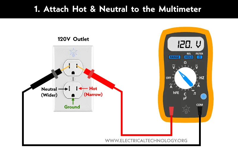
Credit: www.electricaltechnology.org
For repeated ground and current checks, some users may also need a clamp-style meter. Our best clamp meters guide explains when a clamp meter is more practical than a standard handheld multimeter.
Essential Tools Needed
Testing ground with a multimeter requires some basic tools. These tools help ensure accurate readings and safety during the process. Having the right equipment makes the task easier and faster.
This section covers the essential tools needed for ground testing. Each tool plays a specific role in the process. Let’s explore what you need before you start.
Multimeter
A multimeter is the main tool for testing ground connections. It measures voltage, resistance, and continuity. Choose a digital multimeter for clear, easy-to-read results. We recommend the AstroAI Digital Multimeter for reliable ground testing. Make sure it has a continuity test mode for checking ground paths.
Test Leads
Test leads connect the multimeter to the circuit or ground point. They should be in good condition with no broken wires. Use insulated leads to avoid electric shocks. Some multimeters come with test leads, but quality matters. For better contact during ground testing, upgrade to alligator clip test leads for hands-free connections.
Insulated Gloves
Safety is important when working with electrical systems. Insulated electrician gloves protect your hands from electric shock. Use gloves rated for the voltage level you will test. This simple safety tool can prevent accidents.
Wire Stripper
A wire stripper helps expose the metal conductor inside a wire. You need this to connect the test leads properly. It removes insulation without damaging the wire. This tool is useful for making clean and safe contact points.
Screwdriver
A screwdriver is necessary to open electrical boxes or panels. It helps access ground wires or terminals. Use the right size and type to avoid stripping screws. This tool lets you reach the grounding points safely.
Preparing Your Multimeter
Preparing your multimeter is the first step to accurately test a ground connection. Proper setup ensures reliable readings and prevents damage to the device or circuit. Follow simple steps to get your multimeter ready before testing.
Check The Multimeter Battery
Start by verifying the battery level. A low battery can cause incorrect readings. Replace the battery if the display is dim or the multimeter does not turn on. This step saves time and frustration.
Select The Correct Measurement Mode
Turn the dial to the right setting. For ground testing, use the resistance (ohms) or continuity mode. Continuity mode helps detect if the circuit is complete by beeping. Resistance mode shows the exact resistance value.
Inspect The Test Leads
Look over the test leads for damage or wear. Cracked insulation or broken wires may affect the accuracy. Replace faulty leads to ensure safety and correct results.
Calibrate The Multimeter
Some multimeters require calibration before use. Follow the manufacturer’s instructions to zero the meter. Calibration helps maintain accuracy during ground testing.
Setting Multimeter For Ground Testing
Setting your multimeter correctly is key to test ground connections accurately. The right setup helps you find faults fast. It also protects your multimeter from damage. Follow simple steps to prepare your device for ground testing.
Start by switching on the multimeter. Then, choose the right mode for your test. This ensures you get clear and correct readings every time.
Choosing The Correct Measurement Mode
Set your multimeter to measure resistance or continuity. Resistance mode shows how much current can flow through the ground path. Continuity mode checks if there is a complete path for current. Both modes help find breaks or bad connections in grounding.
Setting The Range On Your Multimeter
Use the lowest resistance range available. This setting detects small resistance changes easily. If unsure, start at a higher range then lower it. This prevents overloading your multimeter. Accurate range selection improves test results.
Preparing The Test Leads
Plug the black lead into the common (COM) jack. Insert the red lead into the resistance or continuity jack. Check the leads for damage before use. Good condition leads ensure reliable readings and safety.
Calibrating The Multimeter
Touch the test leads together. The multimeter should read zero or beep in continuity mode. If not, adjust the meter’s zero function. Calibration confirms your multimeter works correctly. It prevents false readings during ground tests.
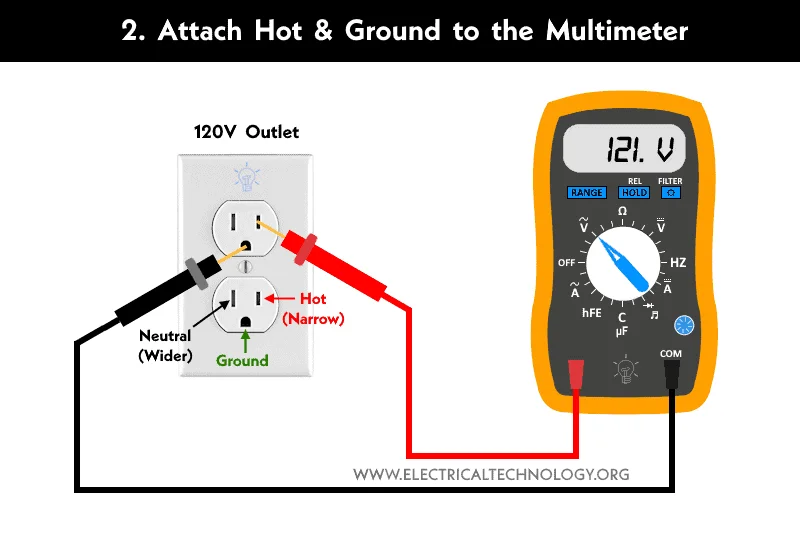
Credit: www.electricaltechnology.org
Locating The Ground Point
Locating the ground point is the first step when testing ground with a multimeter. The ground point acts as the reference for all electrical measurements. Finding it correctly ensures accurate results and safe testing.
A ground point is often a metal part connected to the vehicle or device chassis. It must have a solid connection to the earth or frame to function properly. Identifying this spot carefully prevents errors and helps diagnose electrical issues.
Check The Device Manual For Ground Location
Start by reviewing the device or vehicle manual. Most manuals show the exact ground points. This saves time and avoids guesswork. Manuals often indicate ground symbols and wiring diagrams.
Look For Clean Metal Surfaces
Ground points usually appear as bare metal surfaces. Remove any paint or rust to find a good connection spot. These surfaces should be free of dirt and corrosion for reliable testing.
Identify Common Ground Symbols
Symbols help locate ground easily. A line with three horizontal lines below is a common ground sign. Spot these on circuit boards or near connectors to find ground points quickly.
Use A Multimeter To Confirm Ground
Set your multimeter to continuity or resistance mode. Place one probe on the suspected ground point and the other on a known ground. A reading near zero ohms confirms a good ground connection.
Inspect For Loose Or Damaged Connections
Check the ground point for loose bolts or damaged wires. Tighten bolts and repair any wire damage. A poor connection can lead to false readings and electrical faults.
Measuring Resistance Of Ground Wire
Measuring the resistance of a ground wire is a vital step in checking electrical safety. It shows if the ground wire can carry electricity properly to the earth. Low resistance means a good connection. High resistance may cause electrical faults or shocks.
Using a multimeter to measure this resistance gives clear information. It helps find breaks, corrosion, or poor contacts in the ground wire. Accurate measurement keeps electrical systems safe and working well.
Preparing Your Multimeter For Resistance Measurement
Start by turning off power to the circuit. Set your multimeter to the resistance (ohms) mode. Choose a low range if your meter is not auto-ranging. This prepares the tool for a correct reading.
Connecting The Multimeter To The Ground Wire
Attach the black probe to the ground wire or grounding point. Connect the red probe to a known good earth ground. Make sure probes touch clean metal surfaces for accurate results. Avoid painted or rusty spots.
Reading And Interpreting Resistance Values
Look at the multimeter screen for the resistance value. A good ground wire should show less than 5 ohms. Higher readings suggest poor grounding or damage. If the meter shows infinite resistance, the wire may be broken.
Troubleshooting High Resistance In Ground Wire
Check for loose connections or corroded terminals. Clean contacts with a wire brush if needed. Tighten any loose bolts or screws. Replace the wire if damage or breaks are found. Repeat the test after fixing issues.
Checking Continuity To Ground
Checking continuity to ground is a simple and effective way to ensure a proper electrical connection. It helps confirm that the ground wire is intact and connected without breaks. This step is crucial for safety and preventing electrical faults.
Using a multimeter, you can test the continuity between the ground wire and a known ground point. A good connection will show little to no resistance, indicating a continuous path for electricity. This test helps identify problems like broken wires or poor grounding.
Preparing Your Multimeter For Continuity Testing
Set your multimeter to the continuity mode. This mode often has a symbol like a sound wave or diode. If your meter lacks this mode, set it to the lowest resistance (ohms) setting.
Ensure your multimeter leads are properly connected. Insert the black lead into the common (COM) port and the red lead into the voltage or ohms port.
Find a known good ground on the device or system. This could be a metal chassis, grounding rod, or grounding screw. Make sure the surface is clean and free from paint or rust for accurate testing.
Touch one multimeter lead to the ground point. Hold it steady to get a stable reading.
Testing Continuity Between Ground And Wire
Touch the other multimeter lead to the ground wire or terminal you want to test. The multimeter will beep or show a low resistance number if continuity exists.
A reading close to zero ohms means the ground path is good. You can apply similar techniques when you test a battery with a multimeter. A high reading or no beep means the ground is broken or disconnected.
Interpreting Your Results
Continuous beeping or a low resistance value confirms a good ground connection. This means electricity can safely flow to the earth.
No sound or a high resistance reading indicates a problem. Check for loose connections, corrosion, or damaged wires and fix them before using the system.
Identifying Faulty Ground Connections
Identifying faulty ground connections is crucial for electrical safety and performance. A bad ground can cause equipment failure, electrical shocks, or erratic behavior. Testing ground connections with a multimeter helps find issues quickly. This ensures your system runs smoothly and safely.
Understanding The Role Of Ground Connections
The ground connection provides a safe path for electrical current. It protects people and devices from electrical faults. A faulty ground may not carry current properly, leading to dangerous situations. Knowing how ground connections work helps in spotting problems.
Signs Of A Faulty Ground Connection
Common signs include flickering lights, tripped breakers, or malfunctioning devices. You might also smell burning or see corrosion near ground points. These symptoms suggest the ground connection is weak or broken. Testing confirms the exact issue.
Using A Multimeter To Check Ground Continuity
Set your multimeter to continuity mode or the lowest resistance setting. Connect one probe to the ground wire or terminal. Touch the other probe to a known good ground point, such as a metal water pipe or grounding rod. A reading close to zero ohms means a good ground. High resistance or no continuity indicates a faulty ground.
Inspecting Ground Connections Physically
Look for loose bolts, rust, or damaged wires at the ground point. Clean off any corrosion and tighten connections. Replace frayed or broken wires. A secure, clean connection improves electrical flow and safety.
Measuring Ground Resistance For Accuracy
Use the multimeter’s resistance setting to measure the ground resistance. A good ground typically shows less than 5 ohms. Higher resistance means poor grounding and needs attention. Regular testing keeps your system safe and reliable.
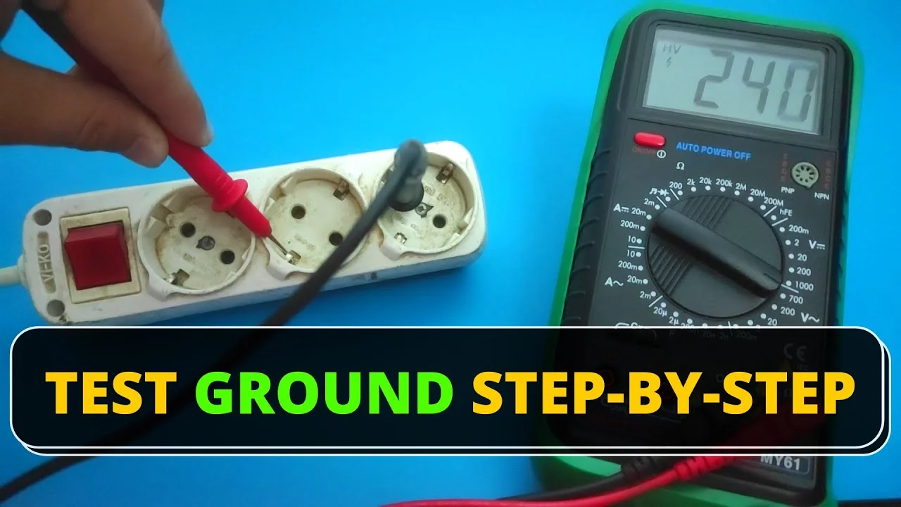
Credit: www.youtube.com
Tips For Accurate Readings
Accurate readings are essential when testing ground with a multimeter. Small mistakes can lead to wrong results and unsafe conditions. Follow simple tips to get precise measurements every time. These tips help avoid common errors and improve your testing process.
Use The Correct Multimeter Setting
Select the right mode on your multimeter. For ground testing, use the resistance (ohms) or continuity setting. This choice ensures the meter measures the connection properly. A wrong setting may give false readings or damage the device.
Check The Probes And Connections
Inspect the test probes before starting. This is as important when you test a motor with a multimeter. Clean and firm probe tips give better contact with metal surfaces. Loose or dirty connections cause unstable readings. Hold the probes steady during measurement to avoid fluctuations.
Test On Clean Metal Surfaces
Remove paint, rust, or dirt where you test the ground. These layers block electrical contact and affect accuracy. Use sandpaper or a wire brush to clean the surface. A clean contact point gives a true reading of the ground connection.
Keep The Multimeter Steady
Hold the multimeter and probes still while testing. Movement can change the reading or break contact. Place the meter on a flat surface for stability. Take your time to get a stable and consistent reading.
Verify The Ground Reference Point
Choose a known good ground point as a reference. This helps compare and confirm your reading. Check multiple points if needed to find the best ground. A proper reference ensures the test results are reliable.
Authoritative External References
For further verification and technical guidance, review these authoritative external resources:
Related testing guides: Ground faults can look like battery, fuse, or motor problems. If the ground test is not enough, review how to test a fuse with a multimeter.
Frequently Asked Questions
How Do You Diagnose A Bad Ground?
To diagnose a bad ground, set a multimeter to continuity mode. Check resistance between the ground wire and a known good ground. A reading near zero ohms indicates a good ground. Inspect connections for corrosion, loose bolts, or damaged wiring to ensure proper grounding.
How Many Ohms Is A Good Ground?
A good ground typically measures 5 ohms or less. Lower resistance ensures effective safety and proper electrical function.
What Is The 3 Point Test For Grounding?
The 3 point test for grounding measures resistance between the ground rod, a reference rod, and a midpoint rod. It verifies grounding system effectiveness.
How To Check If You Have A Good Ground Wire?
Set a multimeter to continuity or low resistance mode. Touch one probe to the ground wire, the other to a known good ground. A reading near zero ohms or a beep indicates a good ground wire. Check for corrosion or loose connections to ensure reliability.
How Do I Test Ground With A Multimeter?
Set the multimeter to continuity or resistance mode. Touch one probe to ground and the other to the wire.
What Reading Shows A Good Ground Connection?
A reading near zero ohms or a beep in continuity mode means a good ground.
Conclusion
Testing ground with a multimeter is simple and important. Always set your multimeter to the correct mode. Check for low resistance to confirm a good ground. A stable ground helps protect your devices and ensures safety. Regularly testing prevents electrical problems and costly repairs. Consider also learning how to use a voltage tester for comprehensive electrical safety.
With these steps, you can test ground wires confidently at home. Practice safe handling and follow instructions carefully. Stay safe and keep your electrical system reliable.